
When Should You Replace Your RF Test Cable? 7 Warning Signs
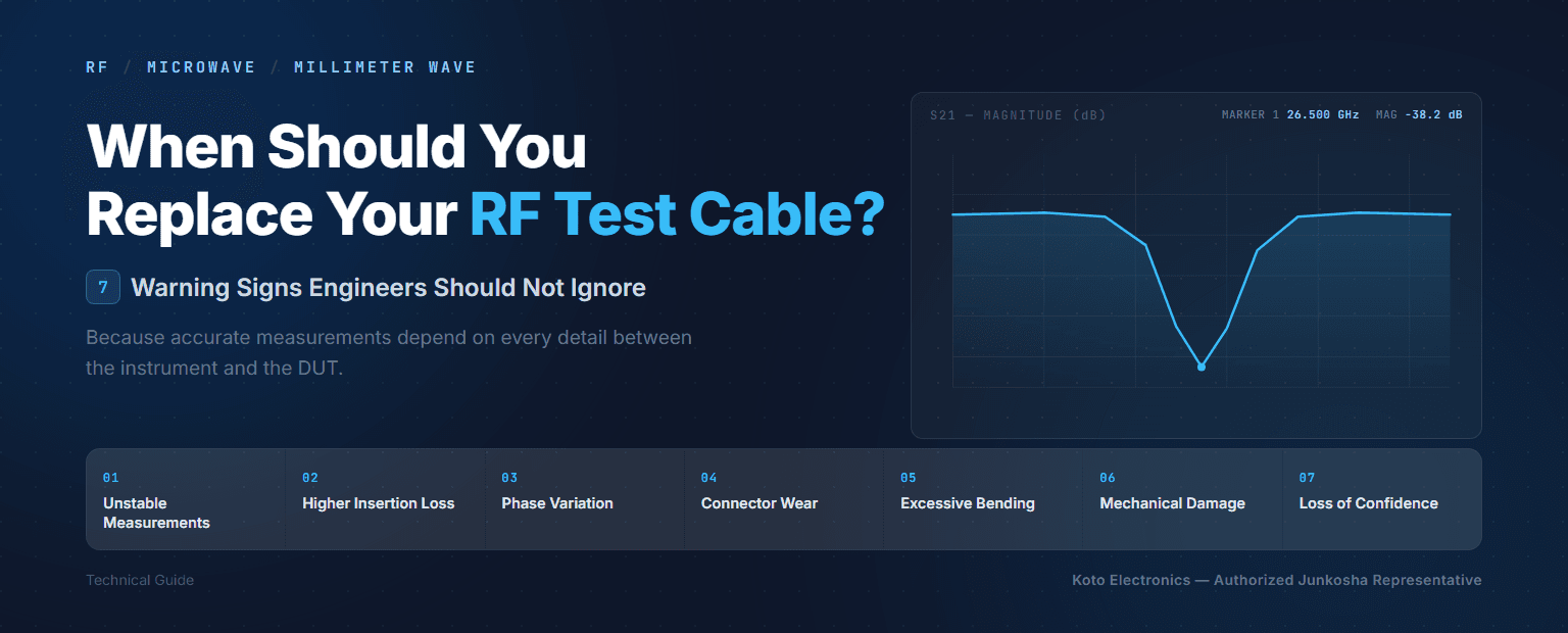
RF test cables are critical components in any microwave measurement setup, yet the cable connecting the instrument to the DUT is often the last thing engineers suspect. A cable does not need to be broken to cause problems — repeated bending, connector wear, and mechanical stress can gradually change its electrical performance while it still looks and feels fine.

While engineers routinely calibrate VNAs, spectrum analyzers, and other test equipment, the cables connecting the instrument to the DUT are sometimes overlooked. Repeated bending, connector wear, mechanical stress, and improper handling can gradually change a cable's electrical performance. It may still appear perfectly functional while introducing additional insertion loss, poor return loss, phase variation, or measurement instability.
At higher frequencies, even relatively small changes can become significant. So how do you know when an RF test cable should be inspected — or replaced?
The 7 Warning Signs at a Glance
| # | Warning Sign | What It Indicates | Quick Check |
|---|---|---|---|
| 01 | Unstable Measurements | Electrical characteristics shift when the cable is flexed | Flex the cable through its normal working range while monitoring the measurement |
| 02 | Higher Insertion Loss | Damage to the conductor, connector, or connector-to-cable transition | Compare against the cable's specification or a previous baseline measurement |
| 03 | Phase Changes When Bent | Dielectric or conductor geometry shifting under flex | Watch the phase trace on a VNA while flexing the cable |
| 04 | Connector Loose or Damaged | Worn threads, center contacts, or interface surfaces | Visual inspection plus a check for correct mating torque |
| 05 | Bent Tighter Than Minimum Radius | Permanent change to the internal cable geometry | Compare the bend against the cable's specified minimum bend radius |
| 06 | Crushed, Twisted, or Mechanically Damaged | Structural damage that is often invisible from the outside | Inspect the area directly behind the connector — the highest-stress point |
| 07 | You No Longer Trust It | Cumulative wear that undermines confidence, even without a clear failure | Remove the cable from the setup and characterize it separately |
The Warning Signs in Detail
1. Your Measurements Are No Longer Repeatable
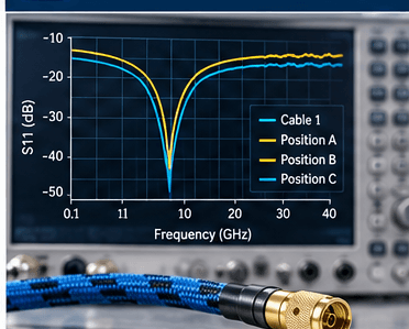
One of the clearest warning signs is poor measurement repeatability — you connect the same DUT several times and get slightly different results, or simply repositioning the cable changes the measurement. Before suspecting the DUT or the instrument, check the cable.
A high-quality RF test cable should maintain stable electrical characteristics when flexed within its specified operating conditions. As a cable ages or becomes mechanically damaged, bending can increasingly affect its insertion loss and phase characteristics. A simple practical test: monitor the measurement while gently moving the cable through its normal working range.
2. Insertion Loss Has Increased
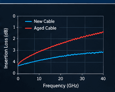
Insertion loss naturally increases with frequency, but it should remain reasonably consistent with the cable's specification and previous measurements. Damage to the cable structure, connectors, or the connector-to-cable transition can increase attenuation — especially important at microwave and millimeter-wave frequencies, where every fraction of a decibel matters.
For example, Junkosha's MWX8 series — built for phase-stable VNA measurements — is characterized at roughly 1.75–2.1 dB insertion loss (MWX821, 635 mm length), a value that should remain stable throughout the cable's life. Periodic characterization of frequently used test cables can help identify degradation before it begins affecting test results.
MWX821 vs. MWX851 — full comparison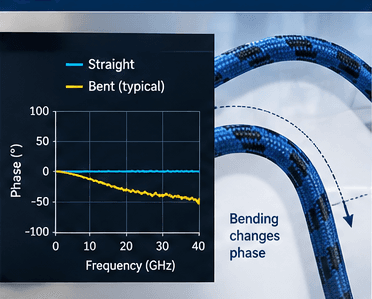
3. Phase Changes When the Cable Is Bent
For many RF measurements, insertion loss is only part of the story — phase stability can be equally important. When a conventional coaxial cable is bent, the physical and electrical relationship between its conductors and dielectric can change slightly, resulting in a change in electrical length and therefore phase.
In applications such as VNA measurements, phase-matched systems, antenna measurements, radar testing, and semiconductor characterization, poor phase stability can introduce significant measurement uncertainty. A useful rule of thumb: 1 ps of delay equals exactly 0.36° per 1 GHz — meaning the same physical deviation translates into a larger phase error as frequency rises.
Picoseconds vs. degrees — the full guide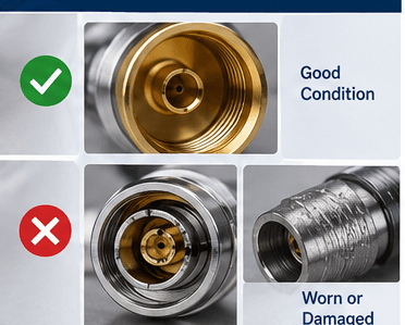
4. The Connector Has Become Loose or Damaged
Very often, the first component to deteriorate is not the cable itself — it is the connector. RF connectors are precision mechanical components, and repeated mating cycles cause wear to threads, center contacts, outer conductors, and interface surfaces.
Look carefully for damaged threads, a loose connector body, contamination, bent contacts, or visible wear. Connector torque matters too — over-tightening can damage the interface, while insufficient torque results in poor electrical contact and degraded return loss. At higher microwave frequencies, very small mechanical imperfections at the connector interface can have a measurable RF effect.
5. The Cable Has Been Bent Too Tightly
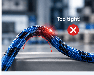
Every RF cable has a specified minimum bend radius. Exceeding this limit can permanently change the internal cable geometry, affecting characteristic impedance, insertion loss, VSWR/return loss, phase stability, shielding effectiveness, and mechanical reliability.
In the standard MWX2 series, for example, the minimum bend radius is roughly 20 mm for armored versions and as little as 6 mm for non-armored ones. A common lab mistake is bending cables sharply behind equipment or forcing them into a small space around the DUT. Even if the outer jacket looks normal, the internal structure may have been damaged.
6. The Cable Has Been Crushed, Twisted, or Mechanically Damaged
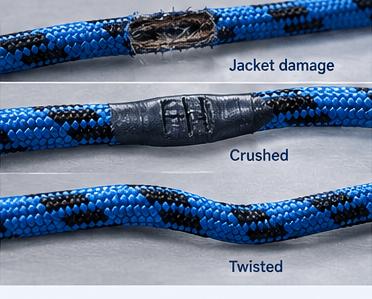
RF test cables are frequently moved between instruments, benches, and DUTs. Over time they may be stepped on, trapped under equipment, crushed by laboratory furniture, twisted during connector installation, or pulled by the cable instead of the connector.
Visible jacket damage is an obvious warning sign, but internal damage can occur without any visible evidence. Pay particular attention to the area immediately behind the connector — this is often subjected to the greatest mechanical stress during normal use.
7. The Cable Passes a Signal — but You No Longer Trust It
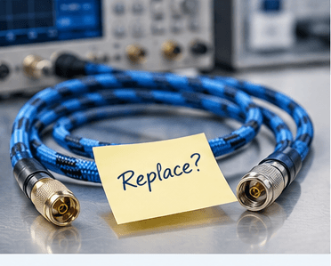
This may be the most important warning sign. A cable does not have to fail completely to become unsuitable for precision RF measurements. If you repeatedly question a cable during troubleshooting, remove it from the measurement setup and characterize it separately.
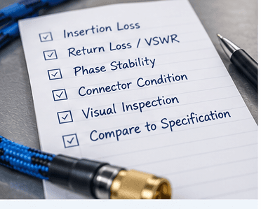
- Insertion Loss — compare measured attenuation with previous measurements or the spec
- Return Loss / VSWR — poor matching may indicate connector damage or internal changes
- Phase Stability — check whether flexing produces abnormal phase variation
- Measurement Repeatability — reconnect and reposition several times and check consistency
Should RF Test Cables Be Replaced After a Certain Number of Years?
There is no universal replacement interval. A cable used occasionally in a controlled laboratory may remain within specification for many years, while another cable used every day in production testing may experience thousands of flex and mating cycles in a much shorter period.
For reference, Junkosha's MWX8 series is rated to exceed 40,000 tick-tock flex cycles at a 180° bend on a 57 mm radius mandrel — a realistic figure for lab use where the cable is repositioned frequently. Replacement should be based primarily on:
Why Cable Quality Becomes More Important as Frequency Increases
At 6 GHz, minor mechanical changes may have limited impact in some applications. At 18, 26.5, 40, 67, 110 GHz and beyond, connector interfaces, cable geometry, and phase stability become increasingly critical. This is why choosing a test cable solely by connector type and maximum frequency is not enough — engineers should also weigh insertion loss, phase stability under flexure, amplitude stability, minimum bend radius, flex life, connector durability, temperature stability, and shielding effectiveness.
The best cable is not simply the one that reaches the required frequency — it is the cable that maintains predictable performance throughout its working life.
Junkosha MWX High-Performance RF Cable Assemblies
Junkosha's MWX series is built for demanding RF and microwave measurement applications, from conventional microwave frequencies into millimeter-wave frequencies above 100 GHz. A key focus of the product family is maintaining stable electrical performance during real-world use, including applications where cables are repeatedly flexed or repositioned.
VNA test assembly, highest-grade phase repeatability
General-purpose microwave assembly, armored and non-armored
D-band and sub-THz assemblies, developed with Keysight
Protect Your RF Test Cables
Good handling can significantly extend the useful life of an RF test cable. And most importantly — periodically verify cables that are used for critical measurements.
The Cost of a Bad Cable Is Often More Than the Cable
High-performance RF test cables are not inexpensive. But neither is engineering time. An unstable or damaged cable can produce misleading measurements, unnecessary DUT troubleshooting, repeated calibrations, and inconsistent test results. In a production environment, it can potentially contribute to false pass/fail decisions.
Replacing a degraded cable is often considerably less expensive than spending hours investigating measurement problems caused by the test setup itself. If your RF measurements have become inconsistent, don't only check the instrument and the DUT — check the cable between them.
Explore the MWX Series
When it's time to replace a test cable, here's a quick overview of Junkosha's MWX series — to help you identify the right model for the swap.
Precision test-grade phase stability — the defining requirement for VNA port cables and high-frequency measurement interconnects.
Slim, durable construction across a wide −55°C to +125°C range — built for rack-and-stack test systems where space is tight.
Flexible with low repulsion force, reducing stress on the DUT during intensive, repeated microwave measurement.
Phase-stable under thermal cycling — the preferred choice for equipment wiring in variable-temperature environments.
Precision skew-matched pairs for differential signaling and high-speed digital measurement.
General-purpose phase-stable cable balancing flexibility and frequency range for everyday microwave work.
Purpose-built for VNA port extension and calibration — the highest phase stability and repeatability grade in the line.
The world's first coaxial cable assembly covering DC to 250 GHz with a 0.5 mm connector, developed with Keysight Technologies.
Need Help Selecting an RF Test Cable?
Koto represents Junkosha high-performance RF and microwave cable solutions in Israel. Send us your requirements — frequency range, connector types, cable length, insertion-loss requirement, flexibility, phase stability, temperature, and application — and we can help identify the appropriate MWX solution for your measurement setup.