
Phase Stable in Flexure. Phase Stable in Temperature. No Compromise.
Most RF cable assemblies make you choose: optimize for flexure stability or optimize for thermal stability. The 7 Series — enabled by Junkosha's ePTFE tape wrapping technology — delivers both, across nine variants from 18 to 67 GHz. Available in Israel through Koto Electronics.
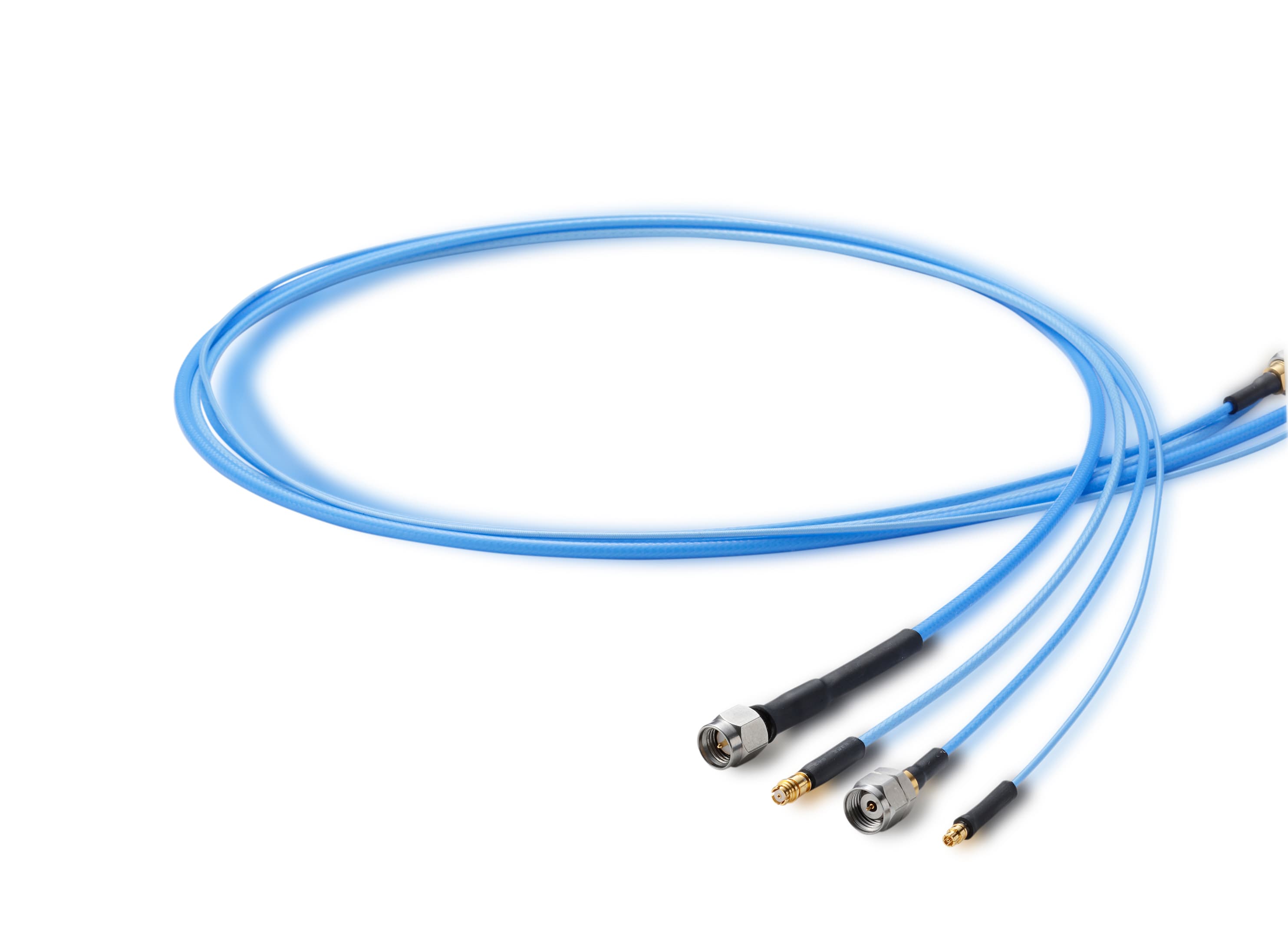
Your Phase-Stable Cable Wasn't Tested in Your Operating Environment
Lab performance and field performance are not the same thing. A cable that holds phase beautifully in a temperature-controlled bench setup may drift significantly when it faces actual deployment conditions — and vice versa.
Flex Stability Without Thermal Stability
Many flexible test cables specify phase stability in flexure — measured at room temperature in a static thermal environment. Deploy the same cable in a system that cycles from −40 °C to +85 °C and the phase behavior changes. The cable you qualified in the lab is not the cable you're flying.
Thermal Stability Without Flex Stability
Conversely, cables optimized for phase stability over temperature often use constructions that are stiffer, have more spring-back, or require careful handling. For instrumentation or system wiring that gets routed, re-routed, and flexed repeatedly, 'thermally stable' alone isn't enough.
Multi-Channel Systems That Drift Apart
Phased arrays and MIMO systems depend on cables that not only hold phase individually, but track each other over temperature. Standard off-the-shelf cables may be matched at 25 °C and diverge by tens of degrees at temperature extremes — errors that appear as beam pointing error or gain imbalance.
ePTFE Tape Wrapping — Stable Everywhere You Need It
Junkosha's engineered ePTFE tape wrapping technology is the core of the 7 Series. Unlike solid or foam PTFE, the tape structure maintains consistent dielectric properties under mechanical stress and across the full −65 to +125 °C temperature range — which is why phase stability in both domains is achievable in a single cable assembly.
- ✓Phase & Amplitude Stability in FlexureBend the cable, route it through a tight radius, flex it repeatedly — the phase response stays consistent. The ePTFE dielectric doesn't compress or shift under mechanical stress the way conventional insulation does.
- ✓Phase & Amplitude Stability Over TemperatureAcross the full −65 to +125 °C range, the cable's electrical length remains stable. Phase change vs. temperature curves measured at 18.5 GHz show well-controlled behavior for all 9 variants — the dielectric's thermal expansion coefficient is managed by the tape construction.
- ✓Genuine Flexibility — No Spring-BackThe cable moves where you put it and stays there. No residual tension on connectors, no cable fighting its own routing. Both the operator and the connected devices benefit from stress-free implementation.
- ✓Nine Variants — 18 / 40 / 67 GHz in Three OD SizesThree frequency bands × three outer diameters (1.2 mm / 1.8–2.2 mm / 3.0 mm) give you a variant for every combination of frequency requirement, space constraint, and loss budget. All nine share the same thermal operating range and ePTFE dielectric technology.
- ✓Broad Connector LibrarySMA, SMP, SMPS, SMPM, 2.92mm, 1.85mm, and 1.0mm connectors are supported across the series — covering instruments from SMA-level VNAs to 67 GHz mmWave platforms.
Factory Phase Matching Options
For radar, phased array, and multi-channel phase-critical applications
A set of two or more assemblies are made within a specified electrical length. The variation within the set is controlled — cables only need to match each other, not a fixed reference. Used in differential and multi-port test setups.
Each assembly is manufactured to a defined electrical length standard. Replacement cables can be ordered individually and will match the installed set without re-characterization. Essential for deployed systems with long service lives.
For radar and phase-critical applications operating in rapidly changing environments. Phase behavior is controlled both within a production batch (intra-lot) and across batches (inter-lot) — cables remain matched over time as the system ages and individual cables are replaced.
Applications
- Phased array radar — multi-channel phase matching
- MIMO and beamforming systems
- Satellite payload and ground station cabling
- Defense electronics — wide temp. range
- General lab and test instrumentation
- Component characterization up to 67 GHz
E11 · E13 · E14 — Up to 18 GHz
Three OD sizes: 1.2 mm (ultra-slim) · 2.2 mm (balanced) · 3.0 mm (lowest loss)
Ultra-slim 1.2 mm — lightest at 5.1 g/m, tight 10 mm bend
2.2 mm OD — best balance of size and loss at 18 GHz
3.0 mm OD — lowest loss in 18 GHz group at 2.4 dB/m
E42 · E43 · E44 — Up to 40 GHz
Three OD sizes: 1.8 mm (slim) · 2.2 mm (balanced) · 3.0 mm (lowest loss)
Slim 1.8 mm — 40 GHz with 10 mm bend radius
2.2 mm OD — 40 GHz, wide connector range
3.0 mm OD — lowest loss in 40 GHz group at 3.9 dB/m
E61 · E62 · E63 — Up to 67 GHz
Three OD sizes: 1.2 mm (ultra-slim) · 1.8 mm (slim) · 2.2 mm (lowest loss)
Ultra-slim 1.2 mm — 67 GHz capable, 5.1 g/m
1.8 mm OD — 67 GHz, 7.7 dB/m
2.2 mm OD — lowest loss in 67 GHz group at 7.2 dB/m
Full Specification Comparison — All 9 Variants
All variants: 50 Ω impedance · −65 to +125 °C · VSWR ≤ 1.44 · Shielding ≥ 90 dB to 18 GHz
| Model | Max Freq. | OD | Mass | VSWR | Ins. Loss (typ.) | Ins. Loss (max) | Vel. of Prop. | Bend Radius |
|---|---|---|---|---|---|---|---|---|
| E11 (047) | 18 GHz | 1.2 mm | 5.1 g/m | 1.43 | 6.3 dB/m | 7.0 dB/m | 79% | 10 mm |
| E13 (086) | 18 GHz | 2.2 mm | 12 g/m | 1.40 | 3.3 dB/m | 3.67 dB/m | 78% | 10 mm |
| E14 (120) | 18 GHz | 3.0 mm | 25 g/m | 1.40 | 2.4 dB/m | 2.6 dB/m | 80% | 15 mm |
| E42 (070) | 40 GHz | 1.8 mm | 10 g/m | 1.43 | 5.7 dB/m | 6.3 dB/m | 80% | 10 mm |
| E43 (086) | 40 GHz | 2.2 mm | 12 g/m | 1.43 | 5.2 dB/m | 5.9 dB/m | 78% | 10 mm |
| E44 (120) | 40 GHz | 3.0 mm | 25 g/m | 1.44 | 3.9 dB/m | 4.4 dB/m | 80% | 15 mm |
| E61 (047) | 67 GHz | 1.2 mm | 5.1 g/m | 1.43 | 13.9 dB/m | 15.6 dB/m | 79% | 10 mm |
| E62 (070) | 67 GHz | 1.8 mm | 10 g/m | 1.43 | 7.7 dB/m | 8.7 dB/m | 80% | 10 mm |
| E63 (086) | 67 GHz | 2.2 mm | 12 g/m | 1.40 | 7.2 dB/m | 8.0 dB/m | 78% | 10 mm |
Typical values. Custom lengths available. Phase matching options on request.
Frequently Asked Questions
What does 'phase stability in both flexure and temperature' actually mean?
What is ePTFE tape wrapping and why does it matter?
What is the difference between relative and absolute phase matching?
What does 'inter/intra lot phase behavior control' mean?
How do I choose between the three OD sizes in each frequency group?
Is the 7 Series suitable for use in defense or aerospace environments?
The MWX Series Family
The full MWX product family covers RF and microwave cable assemblies for every test and measurement application.
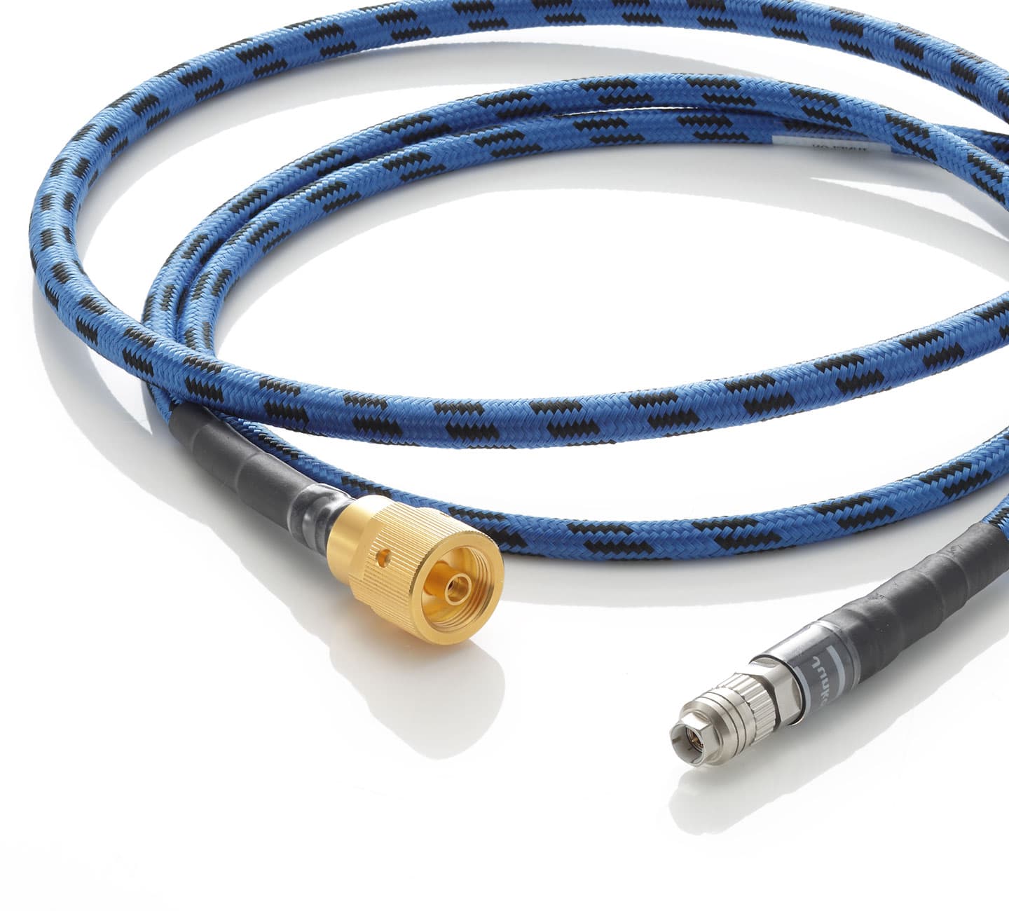
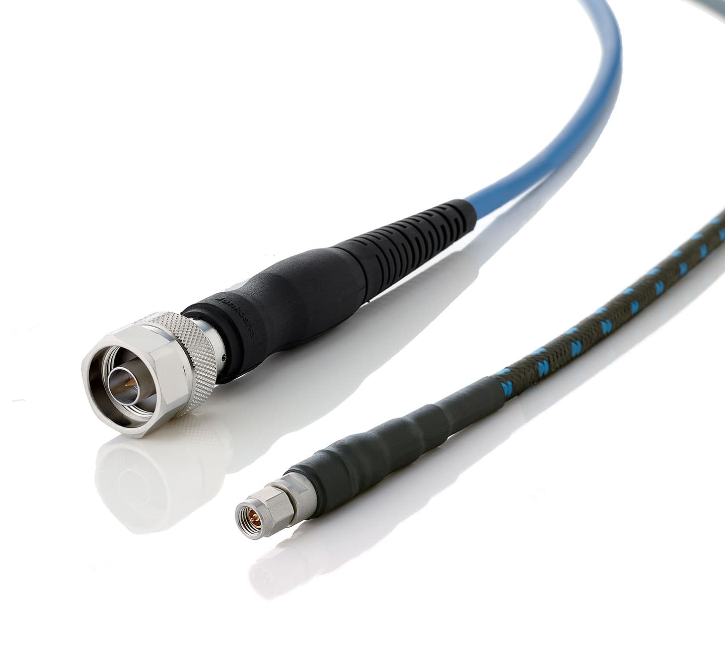
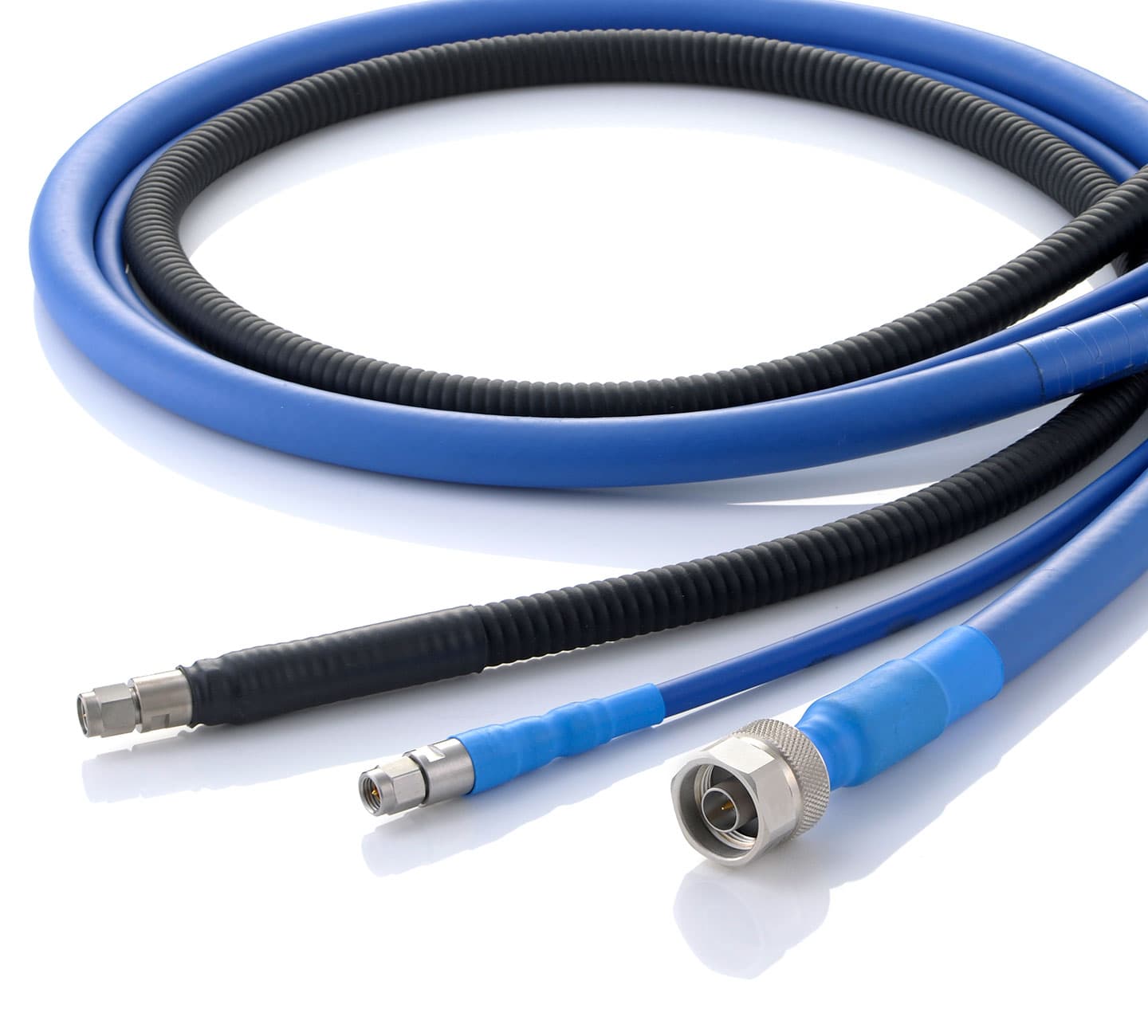
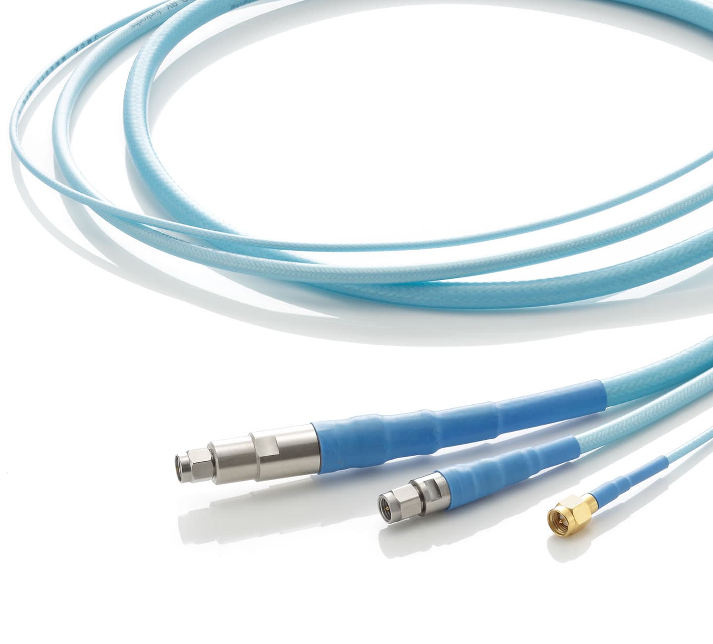
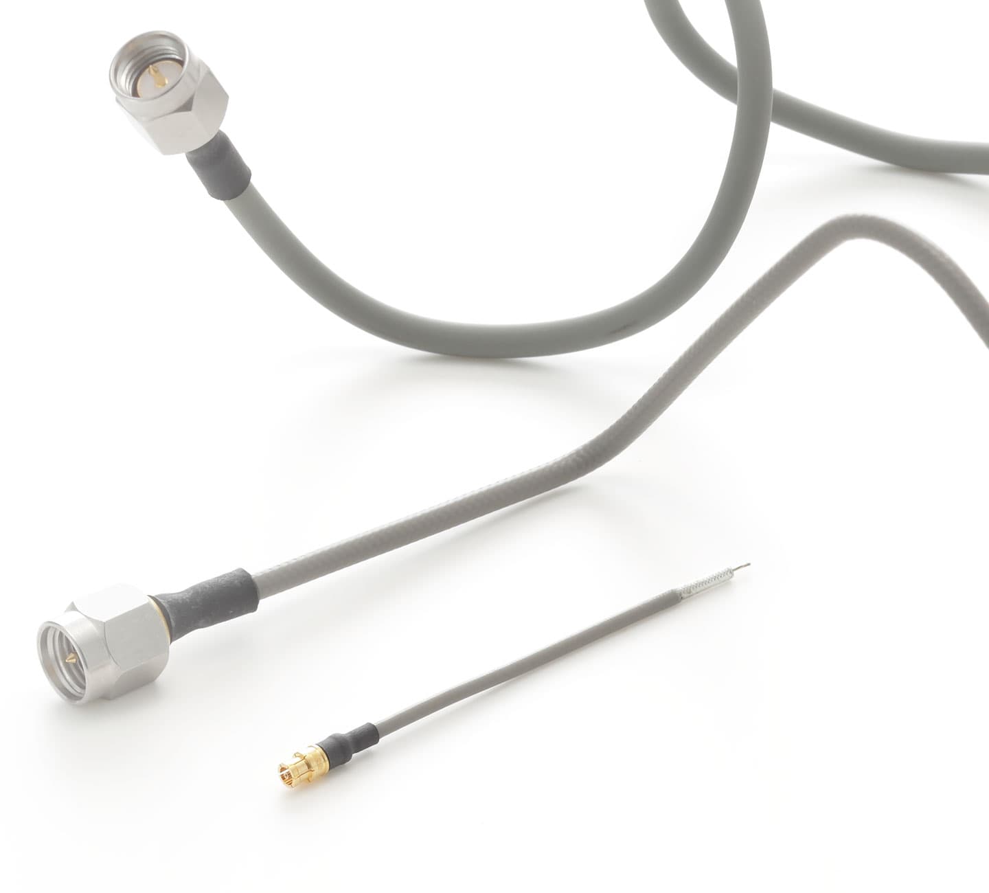
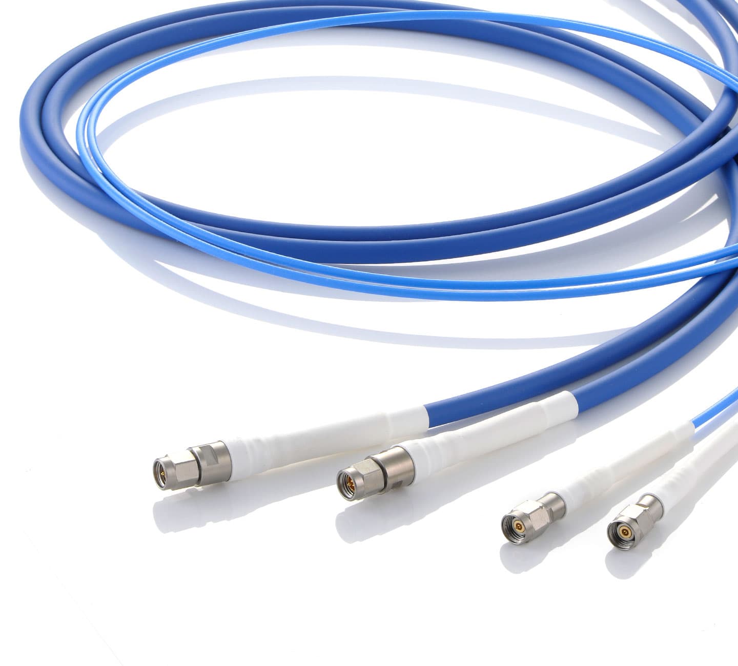
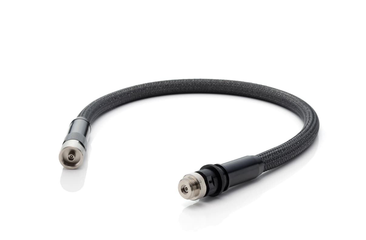
One Cable Series for Every Phase-Critical Scenario
Whether your system flexes in a lab or thermal-cycles in the field, the 7 Series holds phase. Nine variants, factory phase matching, and inter/intra lot behavior control — ready for your most demanding multi-channel application.