
Equipment Wiring That Holds Phase Across Temperature.
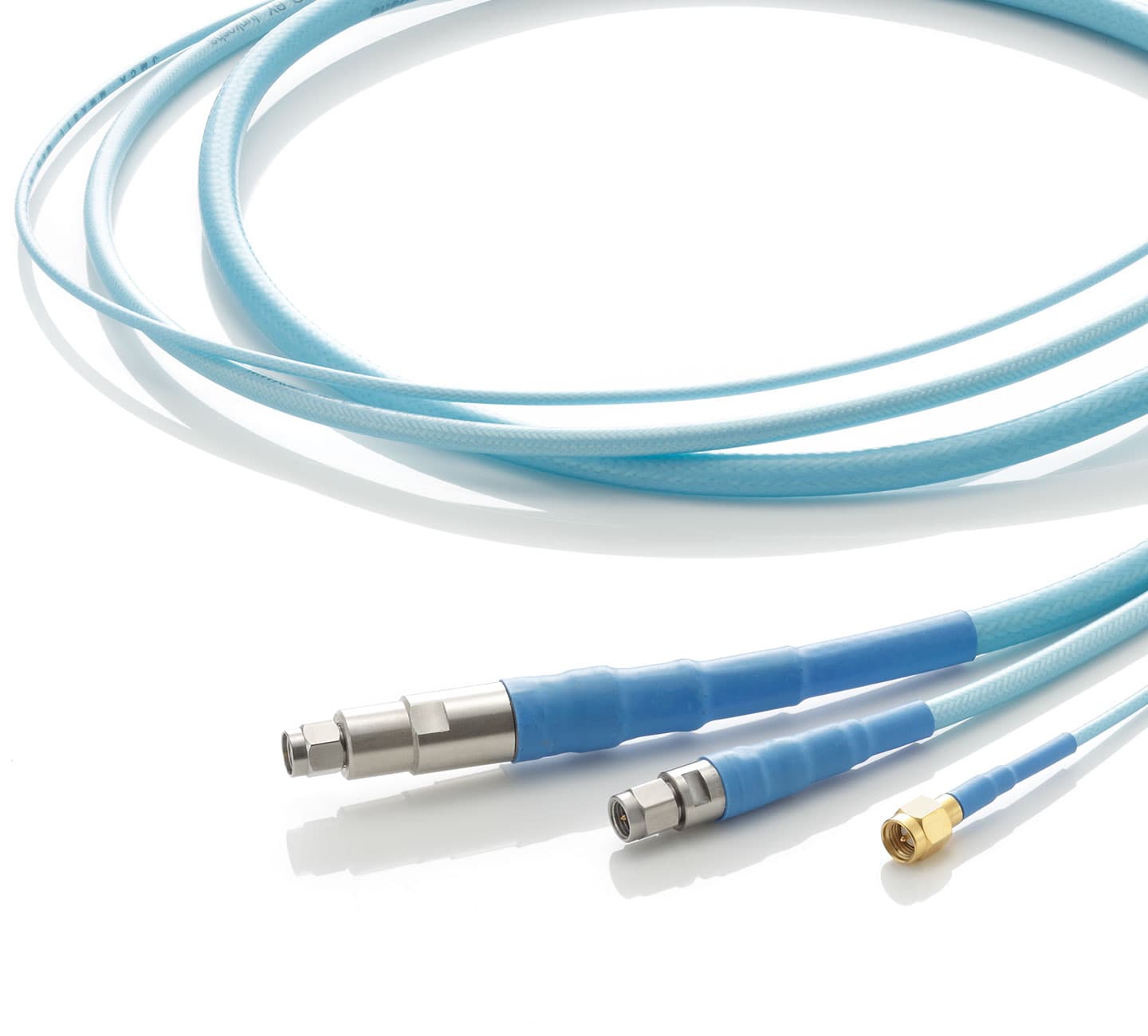
The Junkosha MWX3 Series is engineered for the cables inside your equipment — where temperature cycles and stable phase is not optional. Low Density PTFE dielectric, nine variants from 18.5 to 40 GHz, rated to −65 °C / +125 °C. Available in Israel through Koto Electronics.
When Temperature Changes, Your Cable Lies
Every coaxial cable shifts phase as temperature changes. When that cable is fixed inside your equipment — invisible to the operator — the drift looks like instrument error. It isn't. It's the cable.
Thermal Test Chambers
A cable inside a temperature-controlled test chamber sees −40 °C to +100 °C in a single cycle. If it shifts 10° of phase at 18.5 GHz per metre, a 2-metre run adds 20° of systematic error — error that cannot be separated from the DUT's actual thermal performance.
Instrument Internal Wiring
Inside an RF analyser or signal generator, internal cabling heats as the instrument warms. Generic cables shift phase with temperature. The result is a calibration baseline that moves during the session — a systematic error that grows as the instrument approaches thermal equilibrium.
Satellite & Ground Station Equipment
Outdoor enclosures cycling from desert heat to cool nights demand cables that don't introduce phase noise with the weather. When an internal reference cable drifts, every downstream measurement is wrong — and the source of error is the last place anyone looks.
Phase-Stable. Temperature-Proven. Built for Fixed Wiring.
The 3 Series was designed for this environment — equipment wiring installed once and trusted to perform correctly across the full operating temperature range. Nine variants, three construction types, and assembly lengths up to 20 metres.
- ✓Low Density PTFE — Phase Stable from −65 °C to +125 °CThe PTFE dielectric is the heart of the 3 Series. Low Density PTFE has an exceptionally stable dielectric constant across temperature, which directly determines the cable's phase contribution as it heats or cools. This is the widest rated temperature range in the Junkosha coaxial lineup.
- ✓Nine Variants — 18.5 GHz to 40 GHzFive variants cover the 18.5 GHz band at different OD and insertion loss levels. Two cover 26.5 GHz. Two cover 40 GHz. Across all nine, the 50 Ω impedance and PTFE dielectric are constant.
- ✓Proven Bend Durability — 1,000-Cycle ValidatedThe MWX312 was tested to 1,000 bend cycles with insertion loss and return loss indistinguishable from initial values. Previous-generation products showed degradation at 100 cycles. This matters for cables that may move during maintenance or re-routing.
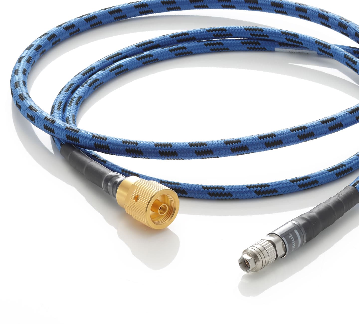
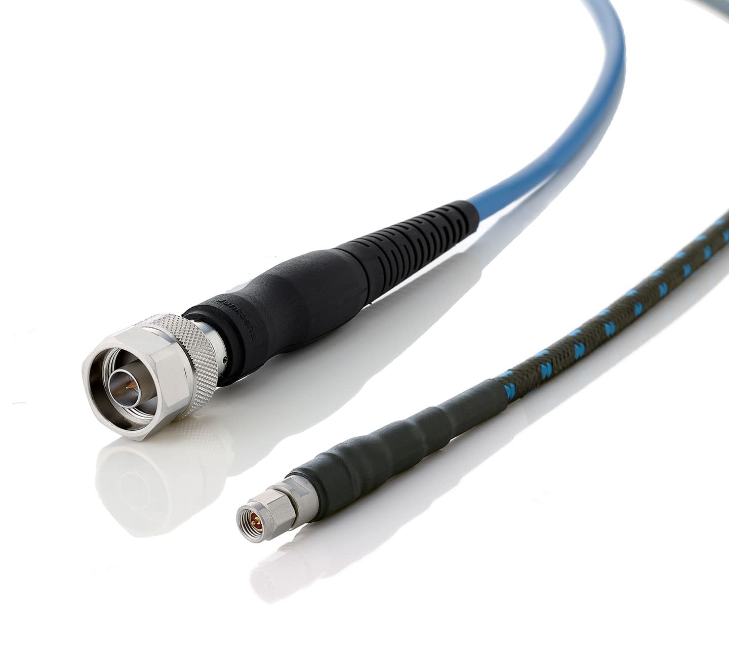
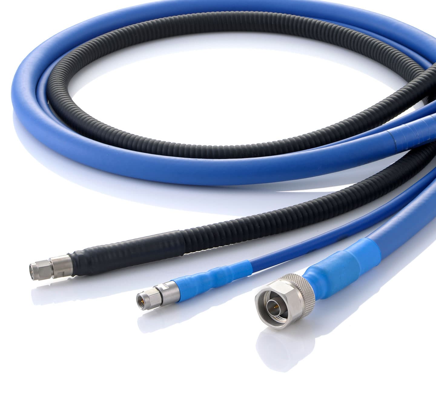
- ✓Three Construction TypesNon-Armored for the lightest and most flexible installation. Armored (/B) with SUS steel spiral tube and wire braid for harsh mechanical environments. Lightweight Armored (/A) for fixed wiring where some protection matters but weight and OD are constrained.
- ✓Up to 20,000 mm — Long Runs Without a JunctionMultiple 3 Series variants ship up to 20 metres as a single assembly. No connectorized junction mid-run, no reflection at a splice. Ideal for large enclosures or equipment where cabling must traverse a significant distance.
Specify and Order in 3 Steps
Local support in Hebrew and English. No international lead times.
Match your frequency and insertion loss budget to the right variant.
18.5 GHz, 26.5 GHz, or 40 GHz? Large OD for low loss, or slim OD for tight routing? Tell us your constraints — frequency, length, construction type — and we will confirm the right model number.
Receive a quote from your Israeli contact.
Koto Electronics handles your order directly. Pricing, lead times, and technical questions answered in Hebrew or English. Matched-phase pairs quoted on request.
Install once. Measure accurately across every temperature cycle.
Low Density PTFE. Wide temperature rating. Proven durability. The 3 Series earns its place in equipment that must be calibrated once and trusted continuously.
9 Variants Across Three Frequency Tiers
All variants share 50 Ω impedance and Low Density PTFE dielectric. Armored and lightweight armored types available for MWX322 and MWX342.
Thinnest at 2.7 mm — 10 mm min. bend, lightest in family
Workhorse — validated to 1,000 bend cycles, up to 20 m
Lower loss than 312 — long internal cable runs
Lowest loss at 18.5 GHz — 0.8 dB/m for high-power or long runs
Absolute lowest loss — 0.76 dB/m, high power rating
26.5 GHz to 20 m — SMA or 3.5 mm connectors
Low loss 1.3 dB/m — armored and lw. armored available
40 GHz in 4.0 mm — compact SMA-terminated runs
Lower loss — 2.4 dB/m at 40 GHz, armored options
Technical Comparison
Standard (non-armored) type specs shown unless noted. MWX315 rated −30 to +85 °C. All values typical at 25 °C.
| Model | Max Freq. | OD | Mass | VSWR | Ins. Loss | Prop. Delay | Vel. | Temp. Range | Max Length |
|---|---|---|---|---|---|---|---|---|---|
| MWX311 | 18.5 GHz | 2.7 mm | 18.5 g/m | 1.40 | 3.4 dB/m | 4.25 ns/m | 79% | −65 to +125 °C | 10,000 mm |
| MWX312 | 18.5 GHz | 4.1 mm | 42 g/m | 1.40 | 2.2 dB/m | 4.10 ns/m | 81% | −65 to +125 °C | 20,000 mm |
| MWX313 | 18.5 GHz | 4.7 mm | 52 g/m | 1.40 | 1.9 dB/m | 4.05 ns/m | 82% | −65 to +125 °C | 20,000 mm |
| MWX314 | 18.5 GHz | 7.7 mm | 125 g/m | 1.40 | 0.8 dB/m | 3.95 ns/m | 84% | −65 to +125 °C | 20,000 mm |
| MWX315 | 18.0 GHz | 8.6 mm | 155 g/m | 1.40 | 0.76 dB/m | 4.30 ns/m | 77% | −30 to +85 °C | 5,000 mm |
| MWX321 | 26.5 GHz | 4.7 mm | 52 g/m | 1.44 | 2.4 dB/m | 4.05 ns/m | 82% | −65 to +125 °C | 20,000 mm |
| MWX322 | 26.5 GHz | 5.2 mm | 60 g/m | 1.33 | 1.3 dB/m | 4.38 ns/m | 76% | −65 to +125 °C | 20,000 mm |
| MWX341 | 40.0 GHz | 4.0 mm | 40 g/m | 1.44 | 3.3 dB/m | 4.05 ns/m | 82% | −65 to +125 °C | 10,000 mm |
| MWX342 | 40.0 GHz | 3.9 mm | 35 g/m | 1.43 | 2.4 dB/m | 4.35 ns/m | 76% | −65 to +125 °C | 10,000 mm |
* All specifications are typical measured values for reference. Contact us for non-standard lengths or matched-phase options.
Frequently Asked Questions
Everything you need to specify and order the right 3 Series cable.
What does 'phase stability: temperature change' mean?
How does the 3 Series differ from the 0 Series for phase stability?
Which variant should I choose for my frequency?
What is the difference between Non-Armored, Armored (/B), and Lightweight Armored (/A)?
Can I get matched-phase assemblies?
What is the longest assembly length available?
The Full MWX Series
RF and microwave cable assemblies for every test and measurement application.
Stop chasing temperature-dependent drift.
Start specifying cables that hold.
The MWX3 Series is available in Israel through Koto Electronics — your authorized local source for Junkosha equipment wiring cables. Nine variants, three construction types, lengths up to 20 metres. Get a quote or talk to our technical team today.